Magnetic particle testing method is suitable for the detection of surface and near surface discontinuities in magnetic material, mainly ferritic steel and iron. The principle is to generate magnetic flux in the article to be examined, with the flux lines running along the surface at right angles to the suspected defect. Where the flux lines approach a discontinuity they will stray out in to the air at the mouth of the crack.
The presence of this leakage field, and therefore the presence of the discontinuity, is detected by the use of finely divided ferromagnetic particle applied over the surface, some of the particle being gathered and held by the leakage field. The crack edge becomes magnetic attractive poles North and South. These have the power to attract finely divided particles of magnetic material such as iron fillings. Usually these particles are of an oxide of iron in the size range 20 to 30 microns, and are suspended in a liquid which provides mobility for the particles on the surface of the test piece, assisting their migration to the crack edges. However, in some instances they can be applied in a dry powder form.
The particles can be red or black oxide, or they can be coated with a substance, which fluoresces brilliantly under ultra-violet illumination (black light). The object is to present as great a contrast as possible between the crack indication and the material background. The technique not only detects those defects which are not normally visible to the unaided eye, but also renders easily visible those defects which would otherwise require close scrutiny of the surface.
MT Techniques : Yokes
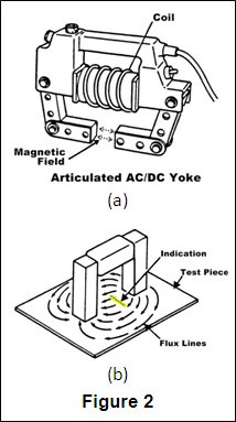
Most field inspections are performed using a Yoke, as shown at the right. An electric coil is wrapped around a central core, and when the current is applied, a magnetic field is generated that extends from the core down through the articulated legs into the part. This is known as longitudinal magnetization because the magnetic flux lines run from one leg to the other.
When the legs are placed on a ferromagnetic part and the yoke is energized, a magnetic field is introduced into the part as shown in (b). Because the flux lines do run from one leg to the other, discontinuities oriented perpendicular to a line drawn between the legs can be found. To ensure no indications are missed, the yoke is used once in the position shown then used again with the yoke turned 90o so no indications are missed. Because all of the electric current is contained in the yoke and only the magnetic field penetrates the part, this type of application is known as indirect induction.
Prods
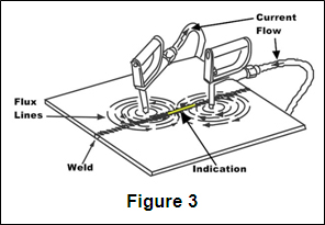
Prod units use direct induction, where the current runs through the part and a circular magnetic field is generated around the legs. Because the magnetic field between the prods is travelling perpendicular to a line drawn between the prods, indications oriented parallel to a line drawn between the prods can be found. As with the yoke, two inspections are done, the second with the prods oriented 90o to the first application.